- 您现在的位置:买卖IC网 > Sheet目录334 > ISL6558EVAL2 (Intersil)EVAL BOARD W/6605 DRVRS ISL6558
�� �
�
�Application� Note� 1044�
�Experimental� Results�
�The� ISL6558EVAL2� evaluation� board� as� configured� is�
�capable� of� 30A� continuous� load� current� and� handling�
�200A/� μ� s� or� higher� speed� load� transients.� The� evaluation�
�board� meets� the� design� specifications� indicated� in� Table� 1.�
�Table� 4� summarizes� the� equipment� that� was� used� for� the�
�performance� evaluation.�
�TABLE� 4.� EQUIPMENT� LIST�
�?� If� there� is� sufficient� airflow,� use� a� single� LPAK� Hitachi�
�HAT1264� for� the� upper� FET� and� two� SO-8� Siliconix�
�Si4842DYs� for� the� lower� FETs� in� each� channel;� but� it�
�comes� with� the� penalty� of� 1%� lower� efficiency,� as� shown� in�
�Table� 5.� Note� that� the� current� sense� resistors� (R2� and�
�R17)� need� to� be� adjusted� to� get� a� proper� over� current�
�setpoint.�
�?� For� 12V� input� operation,� the� jumper� JP1� should� be�
�removed� to� prevent� the� controller� and� drivers� from�
�Equipment�
�Boards� Used�
�Power� Supplies�
�Oscilloscope�
�Multimeters�
�Load�
�Current� Probe�
�Amplifier�
�Fan�
�EQUIPMENT� DESCRIPTIONS�
�ISL6558EVAL2� Rev.� A,� #1� and� #2�
�1.� Hewlett� Packard� 6653A,� 35V,� 15A.� S/N:�
�3621A-03425�
�LeCroy� LT364L.� S/N:� 01106�
�Fluke� 8050A.� S/N:� 2466115� &� 3200834�
�1.� Chroma� 63103.� S/N:� 631030002967�
�2.� Chroma� 63103.� S/N:� 631030003051�
�LeCroy� AP015.� SN:� 3293�
�POPST-MOOREN� TYP� 4600X� (4098547)�
�overvoltage� damage.� A� 5V� supply� is� required� to� power� up�
�the� controller� and� the� drivers;� the� diode� D1� is� to� protect�
�both� the� drivers� and� controller� from� reversed-bias�
�damage.� The� 12V� supply� should� be� applied� prior� to� the�
�5V;� otherwise,� the� output� voltage� will� lack� soft-start� and�
�cause� an� over� overcurrent� or� overvoltage� at� the� output.�
�Furthermore,� the� input� capacitors� should� be� replaced� with�
�higher� voltage� rating� (16V� or� above)� capacitors.� In�
�addition,� the� compensation� gain� (R11)� should� be� scaled�
�by� 5/12� for� system� stability� with� a� reasonable� phase�
�margin.�
�?� Any� change� of� the� output� filter� will� require� the�
�compensation� network� to� change� for� an� optimum� transient�
�response.� If� very� lower� ESR� capacitors� are� used� at� the�
�output,� a� type� III� compensation� network� is� required� to�
�boost� up� the� phase� for� a� better� transient� performance.�
�?� The� feedback� resistor� (R19)� can� cause� some� delay� in� the�
�ISL6558EVAL2� OPERATION� AND� MODIFICATION� TIPS�
�?� Apply� the� input� voltage� (VIN)� prior� to� the� control� voltage�
�VCC5� (5V).� This� sequencing� results� in� initializing� the�
�ISL6609� driver� before� the� ISL6558� starts,� and� retains� the�
�soft-start� interval.� Vice� versa,� the� ISL6558� could� produce�
�maximum� duty� cycle� PWM� drive� signal,� which� results� in� an�
�overcurrent� or� overvoltage� trip� due� to� lack� of� soft-start.�
�The� evaluation� board� is� configured� to� power� up� from� a�
�single� 5V� supply,� and� it� eliminates� the� problem� discussed�
�above.�
�?� SW1� is� used� to� engage� or� remove� the� load� transient�
�generator.�
�?� Droop� option� is� not� selected� in� the� reference� design� since�
�soft-start� interval,� as� discussed� in� the� ISL6557A� data�
�sheet� section� SOFT-START� [3].� It� should� not� be� a� very�
�high� impedance� resistor.�
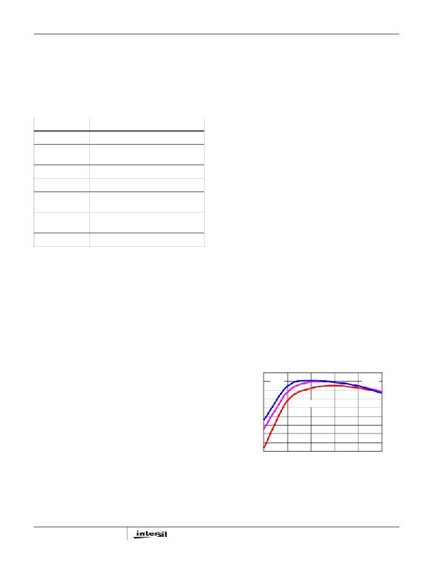
�EFFICIENCY�
�The� efficiency� data,� as� plotted� in� Figure� 3,� are� taken� with� a�
�PAPST-MOTOREN� TYP� 4600X� fan� turned� on� 8”� away� from�
�the� input� end� of� the� evaluation� board� at� room� temperature�
�(approximate� 200LFM).� This� figure� shows� that� the� converter�
�operates� less� efficiently� at� high� line� and� low-to-medium� load�
�since� the� switching� loss� is� the� dominant� portion� of� the� total�
�losses� in� that� operating� condition.� As� the� load� increases,� the�
�dominant� conduction� losses� help� cut� down� the� difference.�
�the� required� load� transient� step� is� not� greater� than� 50%� of�
�the� full� load.� In� another� word,� the� droop� only� helps� reduce�
�the� number� of� output� capacitors� and� still� retains� the� same�
�transient� performance� when� the� load� transient� step� is�
�greater� than� 50%� of� full� load.�
�?� For� 3-phase� operation,� add� the� current� sense� resistor� R17�
�and� place� JP4� to� ON� position� (away� from� TP8).� The�
�compensation� gain� (R11)� should� be� scaled� by� 2/3� for�
�system� stability� with� a� reasonable� phase� margin.�
�92�
�91�
�90�
�89�
�88�
�87�
�86�
�85�
�84�
�4.5V�
�V� IN� = 5.5V�
�5.0V�
�?� For� 4-phase� operation,� add� the� current� sense� resistors� R2�
�&� R17� and� place� JP4� &JP2� to� ON� position� (away� from�
�TP8� and� TP5).� The� compensation� gain� (R11)� should� be�
�83�
�5�
�10�
�15�
�Iout� (A)�
�20�
�25�
�30�
�scaled� by� 1/2� for� system� stability� with� a� reasonable� phase�
�margin.�
�?� Use� R25,� R26,� R28,� and� R29� to� program� the� load�
�transient� speed.� The� higher� values� these� resistors,� the�
�slower� the� transient.�
�4�
�FIGURE� 3.� EFFICIENCY� AT� 500kHz� AND� 200LFM�
�AN1044.2�
�April� 4,� 2006�
�发布紧急采购,3分钟左右您将得到回复。
相关PDF资料
ISL6559EVAL2
EVALUATION BOARD 2 ISL6559
ISL6562EVAL1
EVALUATION BOARD ISL6562
ISL6594BCRZ-T
IC MOSFET DVR SYNC BUCK 10-DFN
ISL6594DCRZ
IC MOSFET DRVR SYNC BUCK 10-DFN
ISL6596IBZ
IC MOSFET DRVR SYNC BUCK 8-SOIC
ISL6597CRZ
IC MOSFET DRVR DUAL SYNC 16-QFN
ISL6605IBZ
IC DRIVER MOSFET DUAL SYNC 8SOIC
ISL6608IR-T
IC MOSFET DRVR SYNC BUCK 8-QFN
相关代理商/技术参数
ISL6558IB
功能描述:IC REG CTRLR BUCK PWM 16-SOIC RoHS:否 类别:集成电路 (IC) >> PMIC - 稳压器 - DC DC 切换控制器 系列:- 标准包装:4,000 系列:- PWM 型:电压模式 输出数:1 频率 - 最大:1.5MHz 占空比:66.7% 电源电压:4.75 V ~ 5.25 V 降压:是 升压:无 回扫:无 反相:无 倍增器:无 除法器:无 Cuk:无 隔离:无 工作温度:-40°C ~ 85°C 封装/外壳:40-VFQFN 裸露焊盘 包装:带卷 (TR)
ISL6558IB-T
功能描述:IC REG CTRLR BUCK PWM 16-SOIC RoHS:否 类别:集成电路 (IC) >> PMIC - 稳压器 - DC DC 切换控制器 系列:- 标准包装:4,000 系列:- PWM 型:电压模式 输出数:1 频率 - 最大:1.5MHz 占空比:66.7% 电源电压:4.75 V ~ 5.25 V 降压:是 升压:无 回扫:无 反相:无 倍增器:无 除法器:无 Cuk:无 隔离:无 工作温度:-40°C ~ 85°C 封装/外壳:40-VFQFN 裸露焊盘 包装:带卷 (TR)
ISL6558IBZ
功能描述:IC REG CTRLR BUCK PWM 16-SOIC RoHS:是 类别:集成电路 (IC) >> PMIC - 稳压器 - DC DC 切换控制器 系列:- 产品培训模块:Lead (SnPb) Finish for COTS
Obsolescence Mitigation Program 标准包装:2,500 系列:- PWM 型:电流模式 输出数:1 频率 - 最大:275kHz 占空比:50% 电源电压:18 V ~ 110 V 降压:无 升压:无 回扫:无 反相:无 倍增器:无 除法器:无 Cuk:无 隔离:是 工作温度:-40°C ~ 85°C 封装/外壳:8-SOIC(0.154",3.90mm 宽) 包装:带卷 (TR)
ISL6558IBZ-T
功能描述:IC REG CTRLR BUCK PWM 16-SOIC RoHS:是 类别:集成电路 (IC) >> PMIC - 稳压器 - DC DC 切换控制器 系列:- 产品培训模块:Lead (SnPb) Finish for COTS
Obsolescence Mitigation Program 标准包装:2,500 系列:- PWM 型:电流模式 输出数:1 频率 - 最大:275kHz 占空比:50% 电源电压:18 V ~ 110 V 降压:无 升压:无 回扫:无 反相:无 倍增器:无 除法器:无 Cuk:无 隔离:是 工作温度:-40°C ~ 85°C 封装/外壳:8-SOIC(0.154",3.90mm 宽) 包装:带卷 (TR)
ISL6558IR
功能描述:IC REG CTRLR BUCK PWM 20-QFN RoHS:否 类别:集成电路 (IC) >> PMIC - 稳压器 - DC DC 切换控制器 系列:- 标准包装:4,000 系列:- PWM 型:电压模式 输出数:1 频率 - 最大:1.5MHz 占空比:66.7% 电源电压:4.75 V ~ 5.25 V 降压:是 升压:无 回扫:无 反相:无 倍增器:无 除法器:无 Cuk:无 隔离:无 工作温度:-40°C ~ 85°C 封装/外壳:40-VFQFN 裸露焊盘 包装:带卷 (TR)
ISL6558IR-T
功能描述:IC REG CTRLR BUCK PWM 20-QFN RoHS:否 类别:集成电路 (IC) >> PMIC - 稳压器 - DC DC 切换控制器 系列:- 标准包装:4,000 系列:- PWM 型:电压模式 输出数:1 频率 - 最大:1.5MHz 占空比:66.7% 电源电压:4.75 V ~ 5.25 V 降压:是 升压:无 回扫:无 反相:无 倍增器:无 除法器:无 Cuk:无 隔离:无 工作温度:-40°C ~ 85°C 封装/外壳:40-VFQFN 裸露焊盘 包装:带卷 (TR)
ISL6558IRZ
功能描述:IC REG CTRLR BUCK PWM 20-QFN RoHS:是 类别:集成电路 (IC) >> PMIC - 稳压器 - DC DC 切换控制器 系列:- 产品培训模块:Lead (SnPb) Finish for COTS
Obsolescence Mitigation Program 标准包装:2,500 系列:- PWM 型:电流模式 输出数:1 频率 - 最大:275kHz 占空比:50% 电源电压:18 V ~ 110 V 降压:无 升压:无 回扫:无 反相:无 倍增器:无 除法器:无 Cuk:无 隔离:是 工作温度:-40°C ~ 85°C 封装/外壳:8-SOIC(0.154",3.90mm 宽) 包装:带卷 (TR)
ISL6558IRZA
功能描述:IC REG CTRLR BUCK PWM 20-QFN RoHS:是 类别:集成电路 (IC) >> PMIC - 稳压器 - DC DC 切换控制器 系列:- 产品培训模块:Lead (SnPb) Finish for COTS
Obsolescence Mitigation Program 标准包装:2,500 系列:- PWM 型:电流模式 输出数:1 频率 - 最大:275kHz 占空比:50% 电源电压:18 V ~ 110 V 降压:无 升压:无 回扫:无 反相:无 倍增器:无 除法器:无 Cuk:无 隔离:是 工作温度:-40°C ~ 85°C 封装/外壳:8-SOIC(0.154",3.90mm 宽) 包装:带卷 (TR)